Theory of Operation
The majority of gasoline-powered four-stroke engines from the 20th century rely upon an ignition coil to generate the spark responsible for igniting the combustion mixture in each cylinder. The ignition coil is an autotransformer separated into primary and secondary windings, all wrapped around an iron core. One terminal common to both windings is connected to the vehicle's battery, often times through a series "ballast" resistor that is bypassed while the vehicle is started so that power to the coil is roughly equivalent between starting and running.
The coil's primary winding is selectively connected to ground through a mechanical switch (called "breaker points") or a power transistor. With breaker points, a capacitor (or "condenser" as it's often called) is placed in parallel to mitigate arcing that can wear the breaker points prematurely. Most auto-makers phased out breaker points in favor of electronic ignition during the 1970s. Figure 4 below shows a schematic representation of the ignition coil's arrangement.
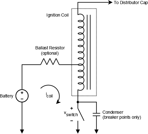
Figure 4: Schematic representation of ignition coil and associated circuitry.
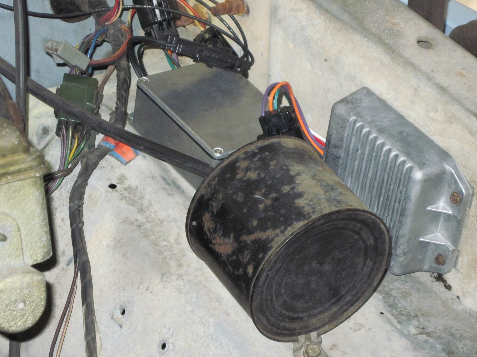
Meanwhile, the coil's secondary winding is connected to the center terminal of the vehicle's distributor cap. Underneath the distributor cap, the rotor pivots about this terminal as a function of the engine's rotation. An electrical contact at the end of the rotor comes into close proximity with each of four, six or eight evenly spaced terminals around the circumference of the distributor cap, shown in Figure 5 below. Each terminal along the circumference of the distributor cap is connected to a spark plug by a length of heavily insulated wire called a plug wire.

Figure 5: Photo showing distributor cap removed to expose rotor (both in blue). The ignition coil can be seen in the upper left of the photo.
To generate a spark at the spark plug, the vehicle's ignition system closes the switch, connecting the primary winding of the ignition coil to ground for a period of time called the "dwell" period. The voltage across the switch, vswitch, is forced to zero as current through the primary winding, icoil, gradually increases. This current is eventually limited by the primary winding's resistance and any ballast resistance in series. Based on a triggering mechanism that is carefully aligned to the position of the engine's crankshaft, the ignition system opens the switch and forces icoil to zero almost instantaneously. This rapid change in current through the inductive primary winding forces vswitch to hundreds of volts (see Figure 6 below).
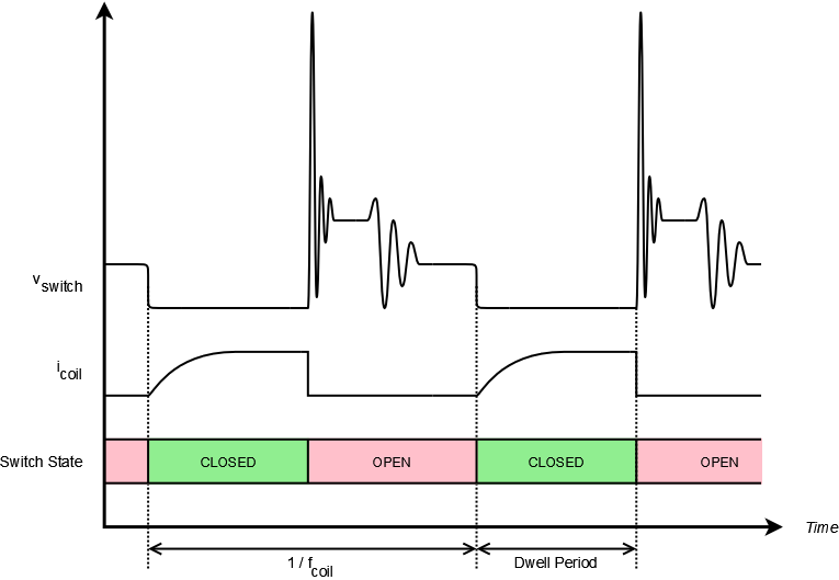
Figure 6: Switch voltage and ignition coil primary winding current as a function of switch state (not to scale).
This voltage spike is then reflected across the secondary winding of the coil in increased orders of magnitude. At this very instant, the distributor rotor happens to be aligned with one of the contacts along the circumference of the distributor cap. The much larger secondary voltage spike jumps across the small gap between the contacts of the rotor and distributor cap, and finally across the electrode of the spark plug.
Both vswitch and icoil are equal in frequency, which we'll call fcoil. The RPM reported by a tachometer is directly proportional to fcoil. Conventional tachometers connect to vswitch and filter the incoming signal to recover fcoil. In the case of a digital tachometer that uses the input capture channel of a microcontroller to measure fcoil, any extraneous or missing edges in the filtered signal can void the measurement. Conditioning vswitch into a transparent logic-level signal is not trivial.
Isn't there an easier way? Recall that an inductor naturally opposes changes in current—so while vswitch is aggressive in nature, icoil is relatively tame. If we focus on icoil instead of vswitch, we're trading for an easier problem to solve—measuring current.
Measuring Current
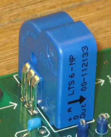
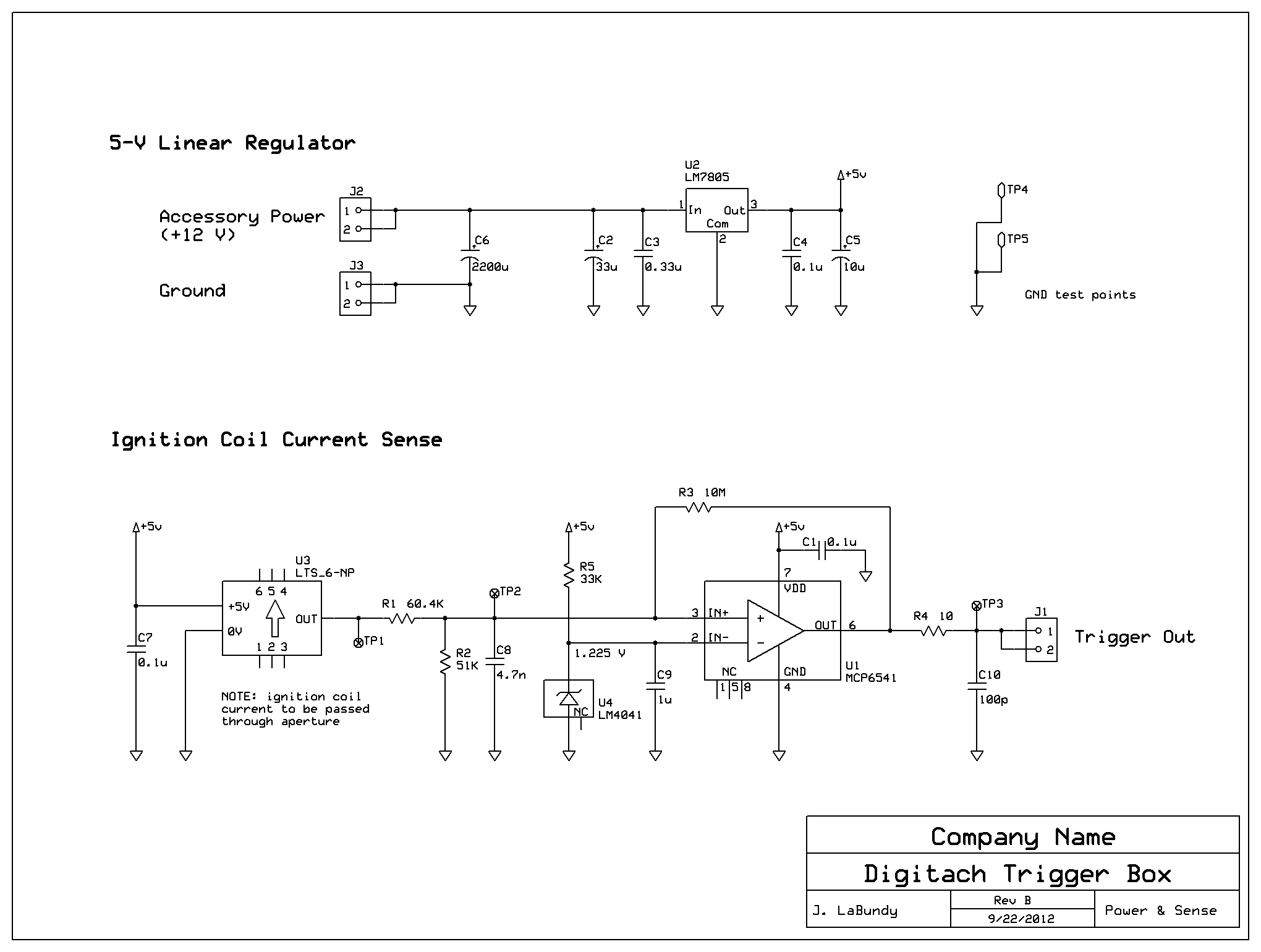
The trigger box measures icoil with an LTS 6-NP closed-loop Hall effect transducer. This PCB-mounted device is powered from a 5-volt supply and drives a single-ended output voltage corresponding to the current passing through its aperture. That output voltage is reported as follows:
vout = 2.5 ± 0.625 × ip ÷ ipn
Where:
- vout = output voltage of the transducer, measured in volts
- ip = primary current (current through the aperture), measured in amp-turns (more on that below)
- ipn = nominal primary current, equal to 6 amp-turns
One "amp-turn" (AT) represents the amount of magnetomotive force generated by one ampere of current flowing through one loop in a vacuum. One loop that carries 6 A represents the same force as three loops that carry 2 A (6 AT). The trigger box directs icoil through the center of the transducer such that its aperture intercepts only one loop. In this case, ip = icoil.
Alternatively, current can be looped through the aperture multiple times by directing current through the transducer's bus-bar pins, which intercept the aperture internally. Additional loops are closed by cross-connecting the bus-bar pins on the PCB. If the bus-bar pins are connected such that current is looped through the aperture three times, ip = 3 × icoil. This scheme increases the dynamic range of the output at the expense of PCB congestion.
Analog-to-Digital Conversion
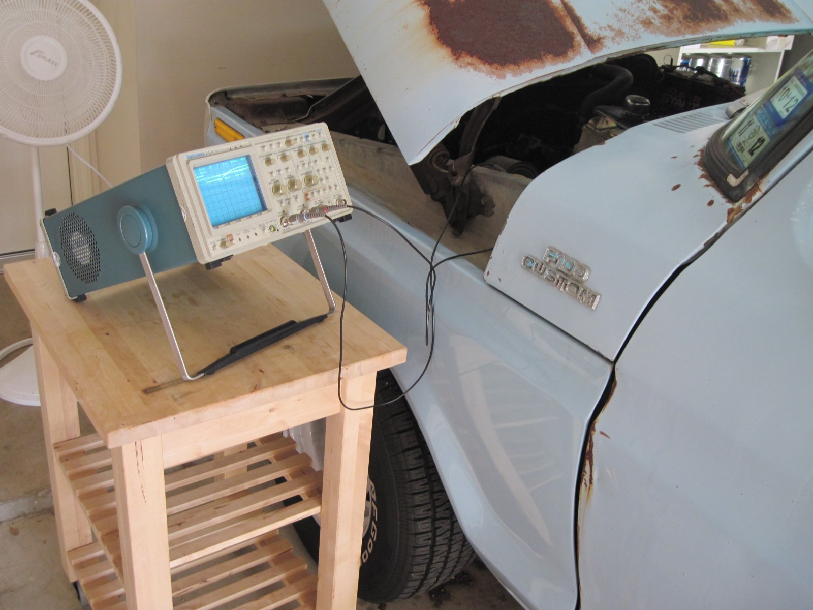
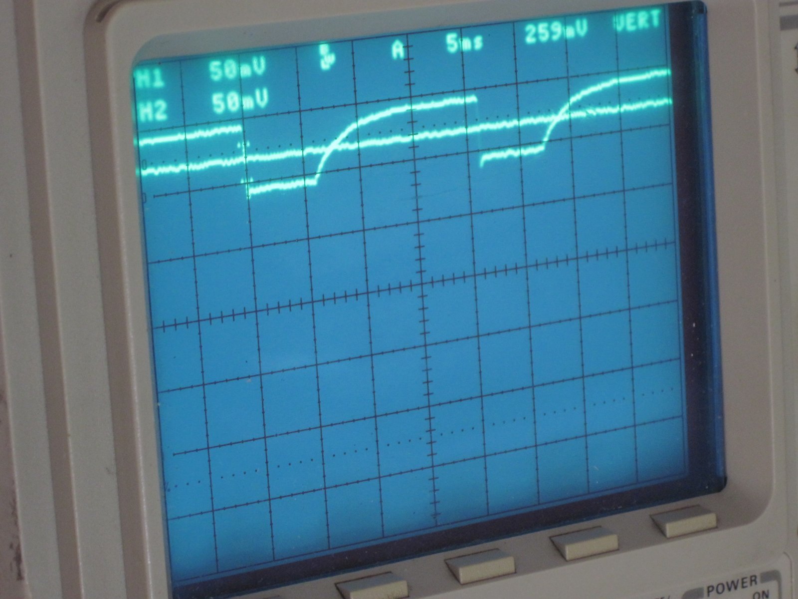
A comparator can generate a logic-level square wave of frequency fcoil by pairing the output of the current transducer with a DC reference. Figure 9 below shows the 5-Vpp output of the trigger box overlaid on top of vswitch taken at the coil using a high-voltage probe—please excuse the poor intensity of the capture.
|


