Theory of Operation
A tachometer reports the number of revolutions per minute (RPM) made by the crankshaft of an engine. In a conventional four-stroke engine, the crankshaft rotates at exactly twice the rate of the camshaft by way of the timing gears, belt, or chain. The distributor shaft rotates at the same rate as the camshaft, as both are directly coupled through a pair of meshed gears. For each full rotation of the distributor shaft, the vehicle's ignition system induces a total of four, six, or eight high-voltage sparks from the ignition coil based on the engine's number of cylinders. The frequency at which the spark is produced, measured in cycles per second (Hz), is therefore directly proportional to engine RPM. This relationship can be expressed as follows:
RPM = 120 × fcoil ÷ n
Where:
- RPM = revolutions per minute
- fcoil = frequency at which the coil produces a spark, measured in Hz
- n = number of cylinders (4, 6, or 8)
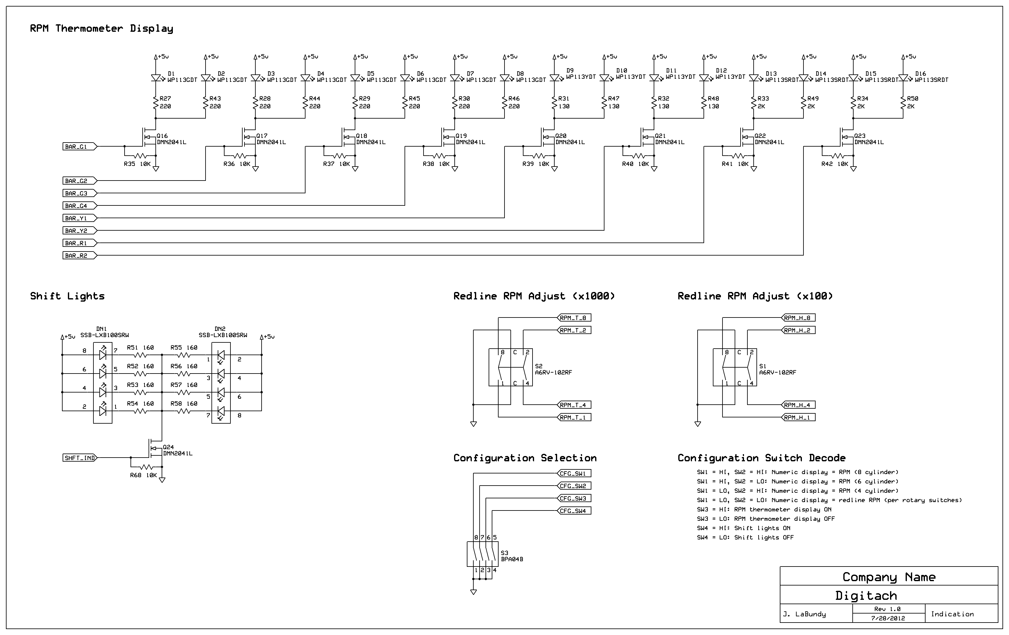
All automotive tachometers essentially measure fcoil. Most aftermarket tachometers are fitted with a switch to indicate the number of cylinders (n) so that the needle movement may be scaled appropriately.
Measuring Frequency
Most microcontrollers include one or more input capture channels that can interrupt program execution in response to the rising or falling edge of an input signal. When used in conjunction with a timer, the input capture channel can measure the frequency of a periodic signal. The signal's period, represented by a counter, is quantized into periods of the timer's clock. If we can find a signal equal in frequency to fcoil and condition it such that it can be safely interfaced to the microcontroller's input capture channel, we can calculate RPM based on the counter. We'll see below that the frequency of the timer clock has a direct impact on the tachometer's accuracy and range.
For a given fcoil, the RPM that is derived from the integer counter may be slightly above or below the engine's actual RPM. This window of uncertainty represents the tachometer's quantization error, which should be minimized for a digital display that can render RPM down to a single digit. Conveniently, quantization error only improves as RPM (and hence fcoil) decrease. This is good news, because idle speed tends to be scrutinized for precision more so than redline.
The quantization error at a given RPM can be reduced by increasing the frequency of the timer clock. Doing so, however, limits the minimum RPM that can be reported because of the finite depth of the timer's counter. If the timer clock is so fast that the counter overflows within one period of the signal represented by fcoil, the measurement is lost. If the engine stalls, the counter overflows indefinitely because fcoil falls to zero.
The timer's overflow interrupt could theoretically be used to track very low RPM by counting the number of times the counter has rolled over, but in practice this is not particularly useful. Most engines idle in the 500 to 700 RPM range, and struggle to run below 400 RPM before stalling. Therefore, it's acceptable to choose the timer clock frequency such that the counter overflows just once, when RPM is too low to matter. Below that point, the display can simply indicate that the engine has stalled.
Figure 4 shows my tachometer's quantization error as a function of RPM for four, six, and eight-cylinder engines. Quantization error is calculated as the difference between actual RPM and the closest quantized RPM that can be resolved from a given fcoil. Each plot has been filtered to appear monotonic by including only RPM that represents the greatest quantization error for a given quantized RPM. The plots stop at the minimum RPM that can be measured before the counter overflows and the tachometer displays the word OFF to indicate that the engine has stalled.
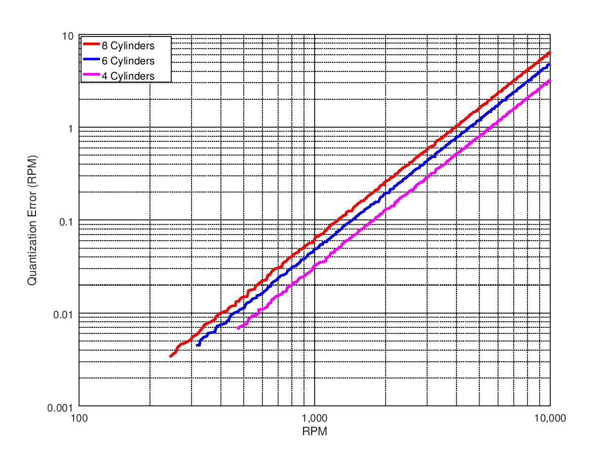
Figure 4: Worst-case quantization error vs. RPM (logarithmic scale)—1.024-MHz timer clock with 16-bit counter.
For my six-cylinder pickup, the quantization error does not exceed the resolution of the display (one RPM) until just after 4,500 RPM. The tachometer can track at least 350 RPM—more than enough margin to set idle speed. The plots show that the tachometer can measure a wider range for an eight-cylinder engine at the expense of a slightly greater quantization error. For a four-cylinder engine, the tradeoff is reversed.
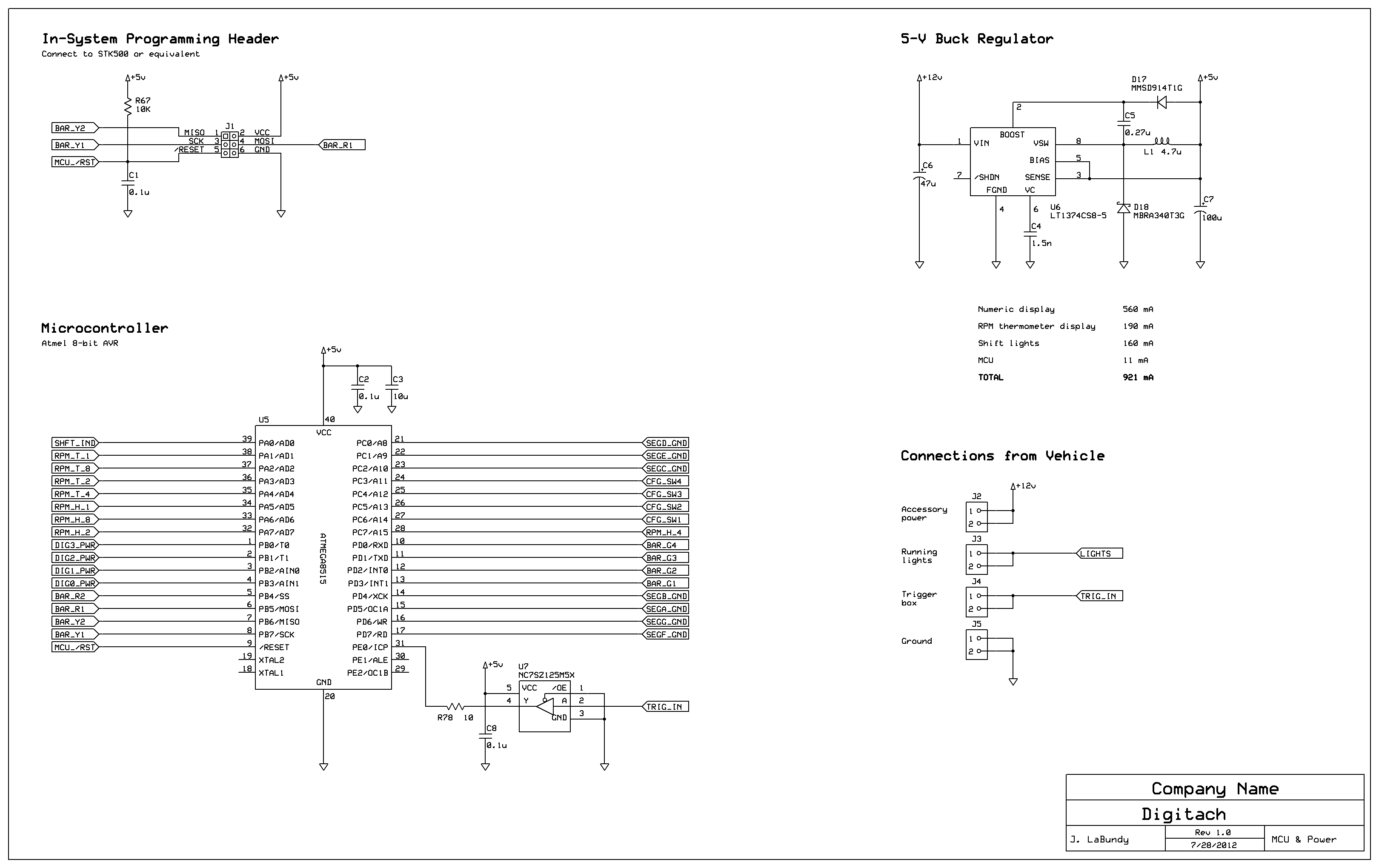
With most microcontrollers, the timer clock is derived from a much faster core clock. The absolute accuracy of the core clock is critical in this application, considering its sole purpose is to in fact measure time. Any inaccuracy in the tachometer's concept of absolute time translates directly to additional error in the RPM that is reported. The first time around, I mistakenly used the microcontroller's internal RC oscillator as the core clock. The RC oscillator's frequency tolerance is specified as ±3%, or ±30,000 ppm—which adds ±140 RPM of uncertainty at 4,500 RPM. Replacing the RC oscillator with a ±50-ppm quartz crystal reduced the error to ±0.5 RPM all the way through 9,999 RPM (not counting quantization error).
Displaying RPM
While a microcontroller can measure RPM with a high degree of accuracy, it's not enough to simply display the raw measurement to the driver. Even at idle, fcoil fluctuates on a cycle-by-cycle basis so much that the lower half of the four-digit display is unreadable without any sort of filtering. The effect is even greater as the driver accelerates and RPM increases.
Therefore, some form of processing has to be added to the display—but that's a tough problem to solve, because the solution is somewhat subjective. Building a naturally moving and readable display that tracks rapid changes in RPM is a trial-and-error process. Any additional filtering needs to be kept as lightweight as possible to minimize latency and maintain accuracy.
I ultimately settled on a two-part solution. First, instantaneous RPM measurements are passed through an eight-sample moving-average filter to swallow minor fluctuations in fcoil. Second, the display is updated only four times per second using the maximum of all the moving averages calculated over the previous 250-ms period. The end result is a display that moves slowly enough to read, while still accounting for large steps in RPM that might occur during a passing maneuver.
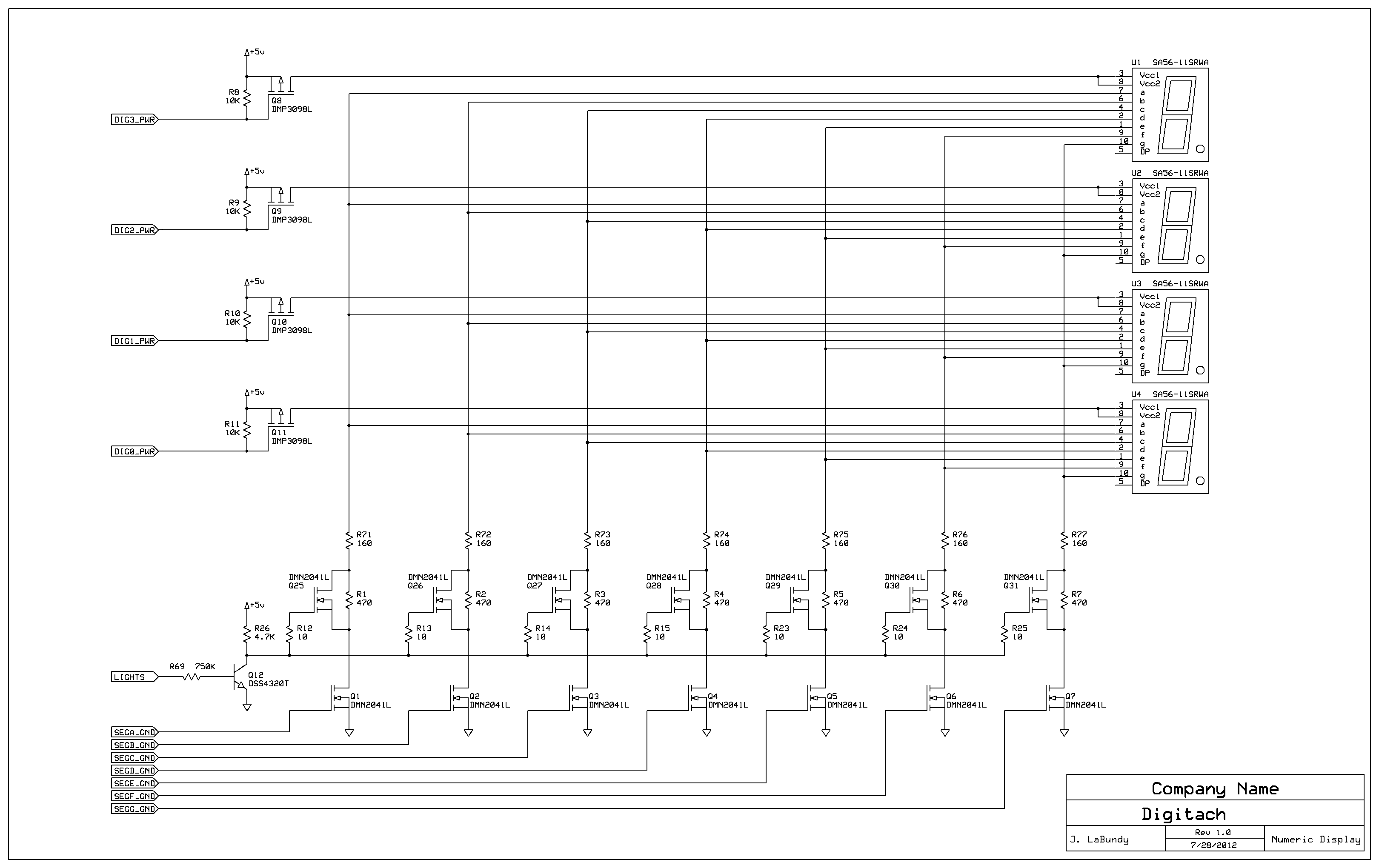
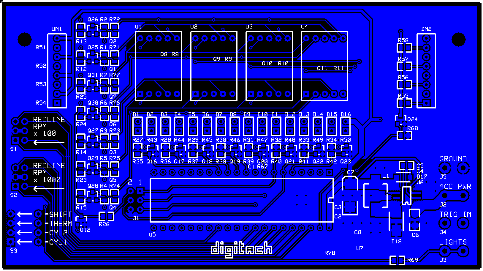
Schematic
|


